


Diesel fuel is one of the most demanding environments a rubber diaphragm can face. This guide covers what engineers and procurement teams need to know — from material selection and sealing geometry to real-world validation — so you stop replacing parts before schedule.
Need a Fuel-Resistant Diaphragm for Your Diesel Pump?
Diesel fuel is one of the most demanding environments a rubber diaphragm can face. This guide covers what engineers and procurement teams need to know — from material selection and sealing geometry to real-world validation — so you stop replacing parts before schedule.
Why Diesel Diaphragms Fail Faster Than They Should
Diesel transfer pumps, injection systems, and fuel management units all depend on one quietly critical component: the flexible diaphragm. When it works, nobody notices. When it leaks or cracks, the consequences range from contamination and downtime to regulatory non-compliance and fire risk.
The frustrating reality is that most premature failures are not caused by a single dramatic event. They are the result of gradual, predictable degradation processes that the right material choice and design could have prevented entirely.
This guide walks through each failure mechanism in depth — diesel soak effects, micro-cracking, sealing geometry, reinforcement strategy, and the validation tests that separate reliable parts from field failures waiting to happen. For a full overview of the diaphragm types DS Rubber supplies, visit our Rubber Diaphragm product page.
1. Diesel Exposure and Long Soak Effects: What Really Happens Inside the Rubber
The Chemistry of Fuel Absorption
When a diaphragm is submerged or repeatedly wetted by diesel fuel, hydrocarbon molecules penetrate the polymer matrix through diffusion. This is not surface damage — it changes the internal structure of the rubber. The lighter aromatic fractions (toluene, xylene) are particularly aggressive because their molecular size is similar to the polymer chain spacing, making uptake faster and deeper.
Over time, absorbed fuel causes the rubber to swell. Swell is measured as a percentage increase in volume or mass after immersion. A material that swells more than 20% under diesel exposure will experience significant changes in its mechanical properties, including a reduction in tensile strength, loss of sealing force, and dimensional distortion. For a detailed breakdown of how these forces interact, see our Rubber Chemical Properties page.
Key Data Point: NBR compounds with low acrylonitrile content (28–34%) can exhibit diesel swell of 30–50% after extended immersion. High-ACN NBR (42–50%) typically shows 8–15% swell. FKM (Viton) grades show < 5% swell even with biodiesel blends. Material selection alone can reduce swell-related failure by an order of magnitude.
Biodiesel Blends and the B20/B100 Problem
Modern diesel fuels are rarely pure. Biodiesel blends — from B5 up to B100 — introduce ester-based compounds that attack a wider range of polymers than conventional diesel. Ester hydrolysis products are acidic and can degrade NBR compounds that would otherwise perform adequately in standard diesel.
If your pump handles biodiesel or you cannot guarantee fuel composition, design for B20 compatibility as a minimum baseline. Specify FKM or HNBR grades that are explicitly rated for ester-based fuels. You can review our full compound matrix on the Material Characteristics page — including resistance ratings for diesel, biodiesel, and other fluids.
Long Soak Conditions: Static vs. Dynamic Exposure
A diaphragm that sits idle in a flooded pump body faces a different chemical threat than one that is constantly flexing and pumping. In static soak conditions, the rubber reaches an equilibrium absorption state. The danger is dimensional change and permanent set that prevents proper sealing when the pump restarts.
In dynamic conditions, mechanical working of the diaphragm continuously drives fuel deeper into the polymer and accelerates extraction of plasticizers. Plasticizer depletion makes the rubber stiffer, which increases mechanical stress per flex cycle and speeds up fatigue cracking. Our Physical Properties page explains how we test and certify hardness, tensile strength, and elongation under both static and dynamic conditions.
2. Micro-Cracking and Stiffness Change: The Slow Failure Nobody Catches
How Micro-Cracks Form
Micro-cracking is the most common diaphragm failure mode in diesel service, and it is almost never visible during routine inspection. Cracks begin at the sub-surface level — typically at reinforcement fabric boundaries, surface tooling marks, or regions of stress concentration around bolt holes and bead radii.
Each flex cycle creates a small tensile strain at the crack tip. In a pristine, well-plasticised compound, polymer chains redistribute this strain. In a fuel-soaked, plasticiser-depleted compound, the material behaves more like hard rubber — brittle at the crack tip, unable to relax before the next cycle begins. The crack advances incrementally. After hundreds of thousands of cycles, it becomes a through-crack, and the diaphragm leaks.
Field Insight: Post-failure analysis of diesel pump diaphragms consistently shows micro-cracks initiating on the fuel-contact side and propagating toward the pressure-contact side. If your failed diaphragm shows cracking on the fuel face, plasticiser loss and swelling-induced stiffness are almost certainly root causes — not just mechanical overload.
Stiffness Change and Its Knock-On Effects
A diaphragm that starts at Shore A 55 and drifts to Shore A 70 after six months of diesel service is not just stiffer — it is a different component. Increased stiffness raises the force required to flex the diaphragm, loading the pump actuator beyond its design intent and causing premature actuator wear.
More critically, a stiffer diaphragm cannot conform as effectively to the sealing surfaces. What was a predictable, repeatable seal geometry becomes variable. Leakage that is initially intermittent becomes persistent as surface conformability continues to degrade. This is why our Pumps industry page highlights material compatibility as the first line of defence in pump seal design.
Measuring and Predicting Stiffness Change
The best way to predict field stiffness drift is an accelerated aging test: immerse the diaphragm in fuel at elevated temperature (typically 70–100°C) for a defined period (72–168 hours), then measure Shore A hardness and tensile properties against the dry baseline. At DS Rubber, we specify that diesel-service compounds must retain hardness within ±5 Shore A points after immersion. Parts that exceed this threshold require reformulation before approval.
3. Sealing Bead Design: The Detail That Makes or Breaks Leak Performance
Why the Bead Matters More Than You Think
Most diaphragm specifications focus on the flex zone — the working area that deforms during pump operation. But in fuel pump applications, the sealing bead is where leakage actually begins. The bead is the raised perimeter ring that compresses against the pump housing to create a fuel-tight barrier. Its geometry determines contact pressure, distribution of sealing force, and how it behaves after repeated compression.
Bead Geometry Principles for Diesel Service
A well-designed sealing bead for a diesel diaphragm should incorporate the following:
- Defined bead height-to-width ratio: A bead that is too tall relative to its width will roll or collapse under compression, creating an uneven sealing footprint. A ratio of approximately 1.5:1 (height to base width) is a reliable starting point for Shore A 55–65 compounds.
- Controlled compression percentage: Target 20–30% compression of the bead height at assembly torque. Under-compression gives inadequate sealing force; over-compression causes creep and permanent set.
- Smooth radius transitions: Sharp corners at the bead base are stress risers that initiate cracking during flexing. Use radii of at least 0.5mm at all bead-to-diaphragm transitions.
- Fuel-side bead sealing: In flooded pump applications, consider co-moulding a FKM bead onto an NBR body if cost constraints prevent an all-FKM design.
Design Note: Beads that look identical in cross-section drawings can behave very differently depending on mould finish and flash trim quality. Specify a maximum Ra surface roughness (typically Ra ≤ 1.6µm on the sealing face) and request inspection records for critical applications. Our in-house lab validates this at every production run — see Our Process.
Compression Set and Bead Relaxation
Compression set is the permanent deformation that remains after a material is compressed for a defined time and temperature. For sealing beads, compression set directly translates into long-term sealing force loss. A bead with 15% compression set after 70 hours at 100°C will have measurably less contact force on day 365 than on day 1.
Low compression set is one of the most important material properties for diesel pump diaphragms. FKM compounds typically achieve 10–20% under demanding conditions. High-ACN NBR achieves 20–30%. General-purpose NBR may be 35–50%. These differences directly explain why leakage rates diverge between material grades after six to twelve months in service. Full property data is available on our Rubber Properties.
Specify a Diaphragm with the Right Compound — Not Just Any Rubber
4. Reinforcement: When, Why, and What Type
The Case for Fabric Reinforcement
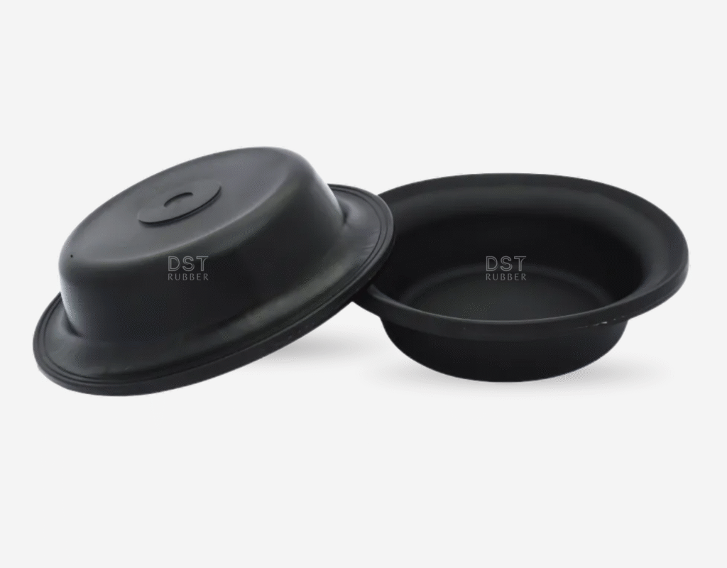
Unreinforced diaphragms rely entirely on the elastomer compound to resist burst pressure and cyclic stress. In diesel fuel pumps — where pressure differentials can exceed 3 bar and cycle rates reach hundreds of thousands per year — fabric reinforcement is not optional.
A woven or knit fabric insert changes the diaphragm from a pure elastomeric membrane to a composite structure. The fabric carries tensile load and limits maximum strain the rubber experiences per cycle. Limiting strain is the single most effective way to extend flex fatigue life. DS Rubber offers both fabric reinforced diaphragms and metal reinforced diaphragms depending on pressure and application requirements.
Fabric Choices for Diesel Service
Not all fabrics are compatible with diesel service. The fabric must bond securely to the elastomer and must itself resist the chemical environment.
- Nylon: Good flex fatigue resistance, moderate fuel resistance. Suitable for most diesel pump applications with proper surface treatment.
- Polyester: Superior dimensional stability and lower moisture absorption than nylon. Often the preferred choice for diesel service.
- Aramid (Kevlar): Exceptionally high strength-to-weight ratio. Resists hydrolysis better than nylon. Used where pressure differential and temperature are extreme.
- PTFE-coated fabrics: Provide a chemical barrier at the fabric-elastomer interface. Useful when using NBR body compounds in aggressive biodiesel environments.
Our full reinforcement philosophy and construction options are documented on the Reinforcement.
Placement and Orientation
In a standard circular diaphragm, a single reinforcement layer is typically placed at or near the neutral plane — the geometrical midpoint of the diaphragm cross-section. This minimises bending stress at the fabric-elastomer interface during flexing.
For high-pressure applications, dual-layer reinforcement provides greater burst resistance but must be designed carefully to avoid creating a stiff mid-section that concentrates all flex strain at the bead radius.
5. Validation Testing: What to Demand Before You Specify
A diaphragm that passes visual inspection and dimensional checks is not validated for diesel service. Genuine validation requires testing that replicates the chemical environment, the mechanical duty, and the thermal conditions your application imposes. The table below summarises the test protocol DS Rubber applies to diesel pump diaphragm approvals. All testing is conducted in our in-house laboratory — certified to IATF 16949 by TÜV NORD.
| Test | Standard | Pass Criteria | Relevance |
|---|---|---|---|
| Immersion Swell Test | ASTM D471 | Volume change ≤ 20% | Diesel / biodiesel blend |
| Flex Fatigue Test | ISO 6943 | 500,000+ cycles | Dynamic diaphragm movement |
| Compression Set | ASTM D395 | ≤ 25% at 70hrs/100°C | Sealing bead performance |
| Low-Temp Flexibility | ASTM D2137 | −40°C crack-free | Cold-start conditions |
| Burst Pressure | Internal | > 4× operating pressure | Safety factor validation |
| Shore A Hardness | ASTM D2240 | Within ±5 of baseline | Post-soak stiffness drift |
Accelerated Life Testing
Because waiting for a part to fail in real time is impractical, accelerated testing uses elevated temperature to speed up aging. Immersion at 100°C for 72 hours represents a significant multiple of real service time at 40°C. Ask your supplier for accelerated life data, not just short-term immersion data.
Why Standard ISO Data Sheets Are Not Enough
Material data sheets report properties of test slabs — flat, uniformly moulded specimens. A finished diaphragm has mould flow lines, fabric-elastomer interfaces, varying cross-section thickness, and residual stresses from the curing cycle. Part-level testing on actual production diaphragms is the only reliable way to validate performance. Slab data is a starting point, not a specification.
6. Field Failure Patterns and How to Fix Them
After analysing field returns from diesel pump diaphragms across multiple industries — including automotive, pump OEMs, and valve and actuator manufacturers — we consistently see five failure patterns. Each points to a specific root cause and corrective action.
Failure Pattern 1: Leakage at the Bead on the Fuel Side
Cause: Compression set on the sealing bead reducing contact force below the minimum needed for diesel tightness. Often accompanied by a visible flat spot on the bead after removal.
Fix: Switch to a lower compression-set compound. Review housing clamp load and torque specification. Consider a bead height increase of 10–15% to provide a longer-term compression reserve.
Failure Pattern 2: Radial Cracking at the Bead Radius
Cause: Stress concentration at a sharp transition between the bead and the flex zone. Cracking is typically on the fuel-contact side, indicating that fuel soak has reduced elasticity in the most highly stressed region.
Fix: Revise mould tooling to add a minimum 0.8mm radius at the bead base. Reformulate to a compound with lower compression set and better fuel resistance. Inspect for tooling flash on the sealing face.
Failure Pattern 3: Delamination of Fabric Reinforcement
Cause: Inadequate bonding agent between fabric and elastomer, or contamination during manufacture. Delamination creates a void that fills with fuel, massively accelerating localised degradation.
Fix: Require your diaphragm supplier to demonstrate adhesion peel strength data (typically > 4 kN/m) for the specific fabric-compound pairing. DS Rubber tests every fabric-compound combination before production approval — see here Our Process.
Failure Pattern 4: Gross Swelling and Dimensional Loss
Cause: Incorrect material specification, or fuel composition change (e.g., introduction of biodiesel blend) without updating the diaphragm specification.
Fix: Audit your fuel supply chain. If composition has changed, requalify the diaphragm material. Consider upgrading to FKM if biodiesel blends are now or may be present. Review the full compound compatibility matrix Check here Material Characteristics.
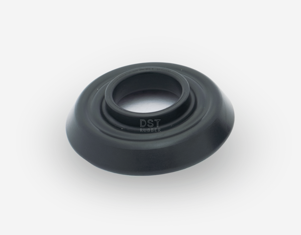
Failure Pattern 5: Centre Hole or Stud Area Tearing
Cause: Stress concentration around the mounting hole during high-cycle operation. Often caused by insufficient tear-stop radius, overly stiff compound, or incorrect torque on the centre stud.
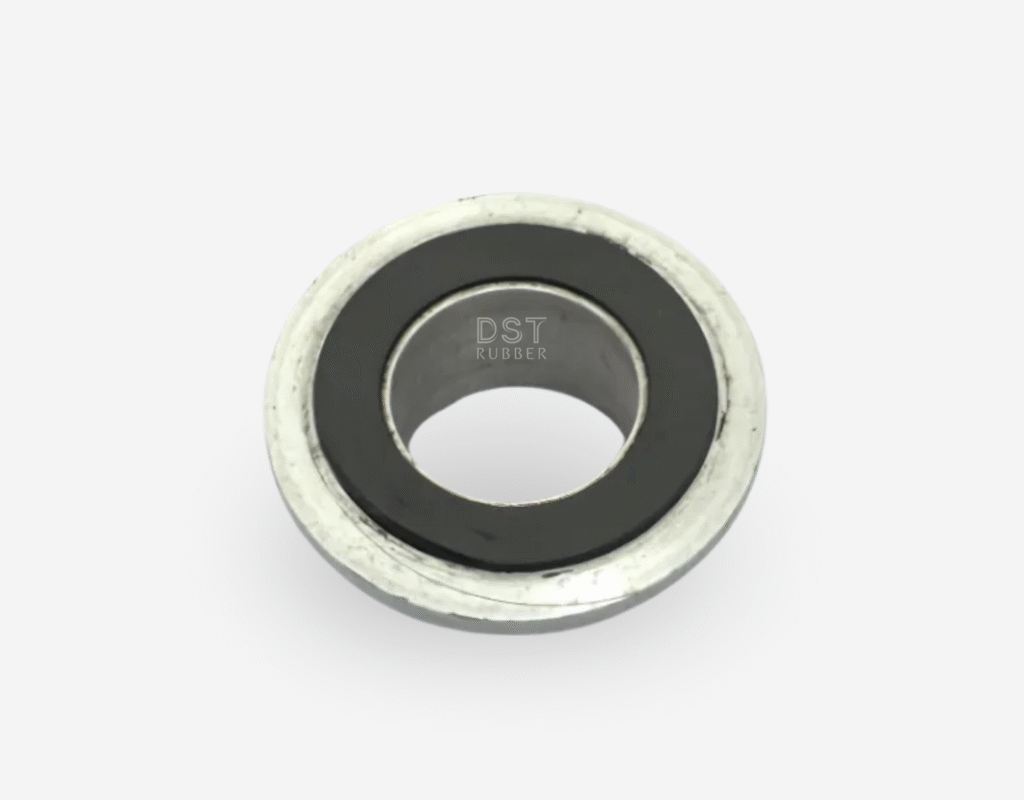
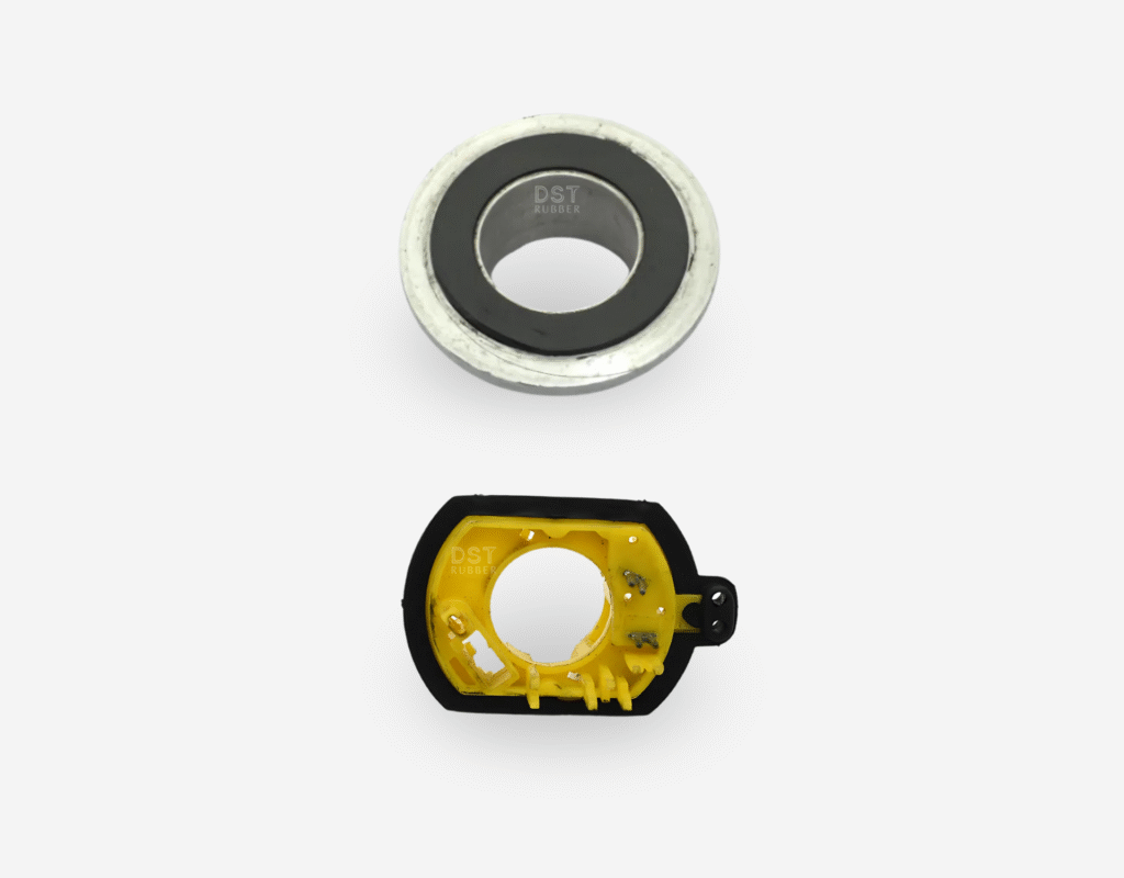
Fix: Add a moulded tear-stop — a thickened annular reinforcement around the mounting hole — to distribute load. Consider a metal insert moulded into the centre area for high-pressure pump applications. See our Rubber-Metal Bonded Parts for metal-insert moulding options.
The DS Rubber Approach: Engineering Reliability Into Every Diaphragm
At DS Rubber, we do not treat fuel-resistant diaphragms as catalogue items. Every diesel pump application involves a material qualification, a sealing geometry review, and a test protocol signed off before first production shipment. With over 35 years of experience and IATF 16949 certification, we supply diaphragms to Ford, Tata Motors, Honeywell, Cummins, and Wika — customers who cannot afford field failures.
Our standard offering for diesel pump diaphragms includes:
- High-ACN NBR and FKM compound options validated for diesel and biodiesel blends up to B100 — see Chemical Properties
- Fabric reinforcement with validated peel strength — Fabric Reinforced Diaphragms
- Metal insert options for high-pressure centre-stud applications — Metal Reinforced Diaphragms
- Full part-level validation per the test protocol above — certified to IATF 16949
- Proven performance in pump and valve OEM applications — Pumps industry page | Valves & Actuators
- Traceability documentation, compound certificates, and test reports with every shipment
Case Study — Fuel Regulator Diaphragm: DS Rubber developed an ultra-thin 0.20mm diaphragm for LPG/CNG fuel regulator systems that required both fuel resistance and precise flex performance. The same engineering disciplines applied to diesel pump diaphragms. Read the full case study.
Frequently Asked Questions
What rubber is best for diesel fuel diaphragms?
FKM (Viton) offers the highest resistance to diesel and biodiesel blends. High-acrylonitrile NBR (42–50% ACN) is the most common cost-effective choice for standard diesel. HNBR is a good option where both heat resistance and fuel resistance are required. Review compound options here Material Characteristics.
How do I know if my failure is material-related or design-related?
Material failures typically show uniform degradation, swelling, softening or hardening, and crack patterns distributed across the flex zone. Design failures tend to show localised damage — cracks concentrated at a single radius, tearing at a bolt hole, or delamination in a specific region. DS Rubber offers failure analysis as part of our engineering support.
Can I use the same diaphragm for diesel and petrol service?
Not reliably. Petrol contains different aromatic fractions than diesel and is more aggressive toward NBR compounds. A diaphragm validated for diesel should be requalified for petrol service. FKM handles both fuels well, but part-level testing for each application is still recommended.
What service life should I expect from a quality diesel pump diaphragm?
With the right material and design, a well-engineered diesel pump diaphragm should achieve 2–5 years of continuous service or 1–2 million flex cycles in typical industrial applications. Diaphragms that fail in under 12 months almost always indicate a material mismatch or manufacturing defect — both preventable.
Does DS Rubber supply custom diaphragms for non-standard pump dimensions?
Yes. DS Rubber specialises in custom-moulded rubber components. We can manufacture your drawing, to a sample, or assist with design-to-specification. Visit our custom rubber products or send your drawings directly.
Related Products from DS Rubber
If you are specifying or replacing components in a diesel fuel system, these DS Rubber product pages may also be relevant:
- Rubber Diaphragms — full range including fabric and metal reinforced
- Rubber Gaskets — companion sealing components for pump housings
- O Rings — precision sealing elements for fuel system interfaces
- Rubber Seals — static and dynamic sealing for pump bodies
- Rubber-Metal Bonded Parts — for centre-insert and flange-bonded diaphragm assemblies
- Rubber Bellows — flexible sealing for moving fuel system connections
Ready to Eliminate Diesel Diaphragm Failures?
Send us your application details — fuel type, pressure, temperature, cycle rate, and current failure mode. Our engineers will respond within 24 hours with a validated material recommendation and quote. DS Rubber: 35 years, zero customer-end rejections, IATF 16949 certified.